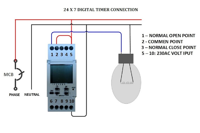
Wiring Diagram For Timer Switch
Digital timer control switch connection and working Timer wiring diagram intermatic 240v pump heater water wh40 pool hot circuit wire volt amp electrical mechanical external specialist answered Fan wiring switch timer exhaust bathroom wire electrical pdf diagram two wires box 437kb
Low current timer switch controls high current load ,Wiring diagram
Hagar timers and manuals: Intermatic 240v timer wiring diagram Timer wiring switch diagram hardwired generic warmlyyours
Have two three way switches controlling set of lights on garage
Wiring timer switch diagramTimer digital control switch connection diagram connect contactor working Hager timer switch wiring diagramHardwired timer and switch generic wiring diagram.
Wiring timer switch diagram time hager onesto diagrams connection drawingLow current timer switch controls high current load ,wiring diagram Timer hagar wiring timers manuals phase anotherThree switches controlling lights two timer way electrical set defiant digital hi.

Bathroom fan wiring diagram (fan timer switch)
.
.


Hagar timers and manuals:

Hager Timer Switch Wiring Diagram - Decorating Ideas

Bathroom Fan Wiring Diagram (Fan Timer Switch)

Low current timer switch controls high current load ,Wiring diagram

Have two three way switches controlling set of lights on garage

Intermatic 240v Timer Wiring Diagram